Airhead tranny 'circlip failure'
For about ten years ('85-'94 roughly) BMW omitted a circlip from the front of the output shaft, and didn't cut the corresponding groove for installing it. This allows the front bearing to be pushed out of position by the fifth gear, causing excessive preload and eventual failure. The fix is to cut a groove in the shaft and reassemble the transmission with a circlip. If the shaft is damaged at the 5th gear interface or at the taper, replacement is also an option. New shafts have the circlip groove cut in them, as did the older shafts.
The transmission has three shafts: input, intermediate and outupt. At the front of all three of them is a helical gear; the input and intermediate gears are always in use and the output gear is under load when running in fifth gear. The input gear is held in place by the shock coupler, the intermediate gear is fixed to the shaft, but the output shaft gear is only held in place by the bearing that is pressed on in front of it. The sideways load on the helical gear (the angled teeth natually generate a sideways load) works against the bearing and slowly pushes it out of place. This leads to a constant and excessive bearing side loading which eventually destroys the bearing. If the bearing actually falls apart, things get radically out of position and the damage spreads.
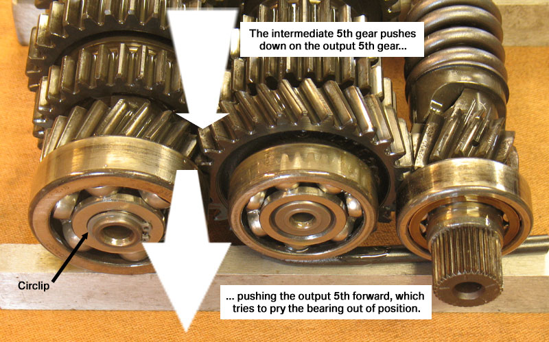
Normally the shafts (with bearings on each end) are installed with about 0.10mm of clearance. When you turn either the input or output shaft, it will spin smoothly (with some drag due to the seals and internal friction, but smoothly). When this problem develops, the movement becomes notchy, although it may be difficult to detect with the transmission installed, and you may hear a rumbling noise from the bearing.
Ever wondered how the circlip failure really manifests itself? Here are a few pictures. This is from a customer bike that was in for a crankshaft replacement, and I noticed the stiff output shaft while cleaning the transmission.


Normally I do this in the press but this was more dramatic. That, and the press was so cluttered I was embarrassed to photograph it.
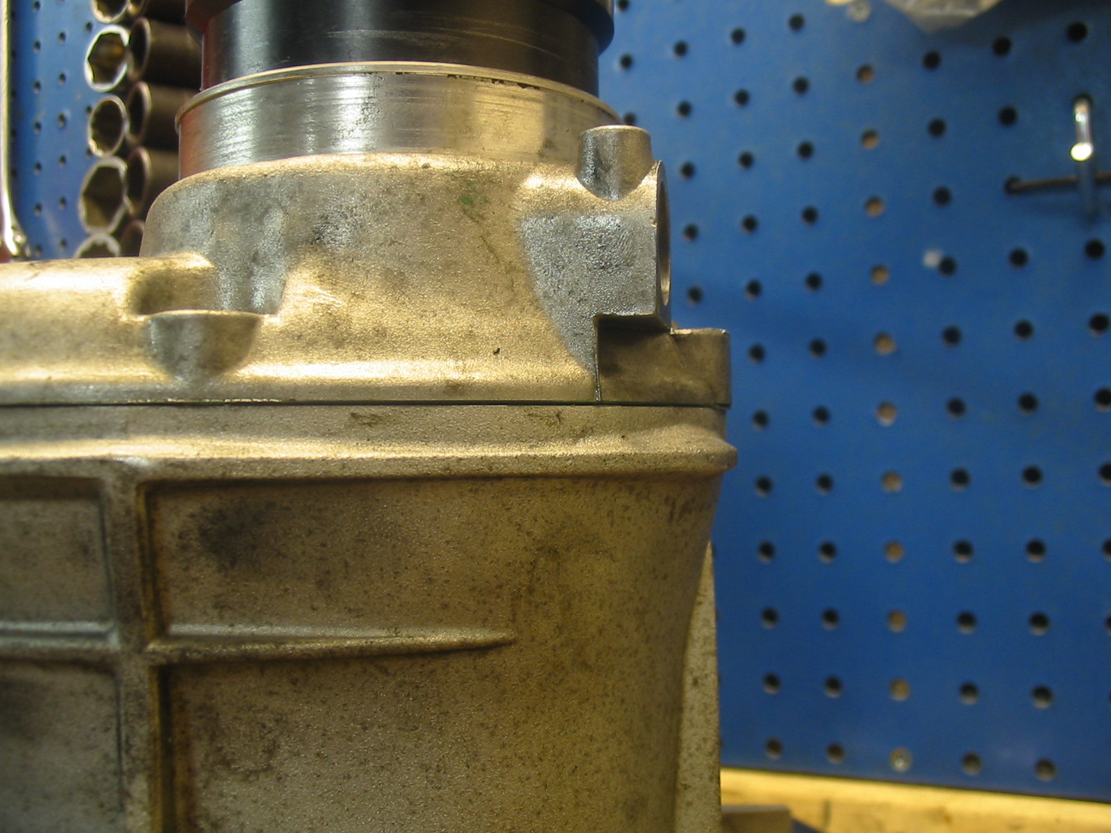
5) Here is a plain vs. circlip shaft. The bearing normally seats against the first step, but you can see from the 'grime line' how it was farther out on the non-circlip shaft. Due to the radius in the bearing inner race, the 'grime line' is not all the way back at the step even when the bearing hasn't shifted.
It is this inner exposed part that you can see in the second photo.
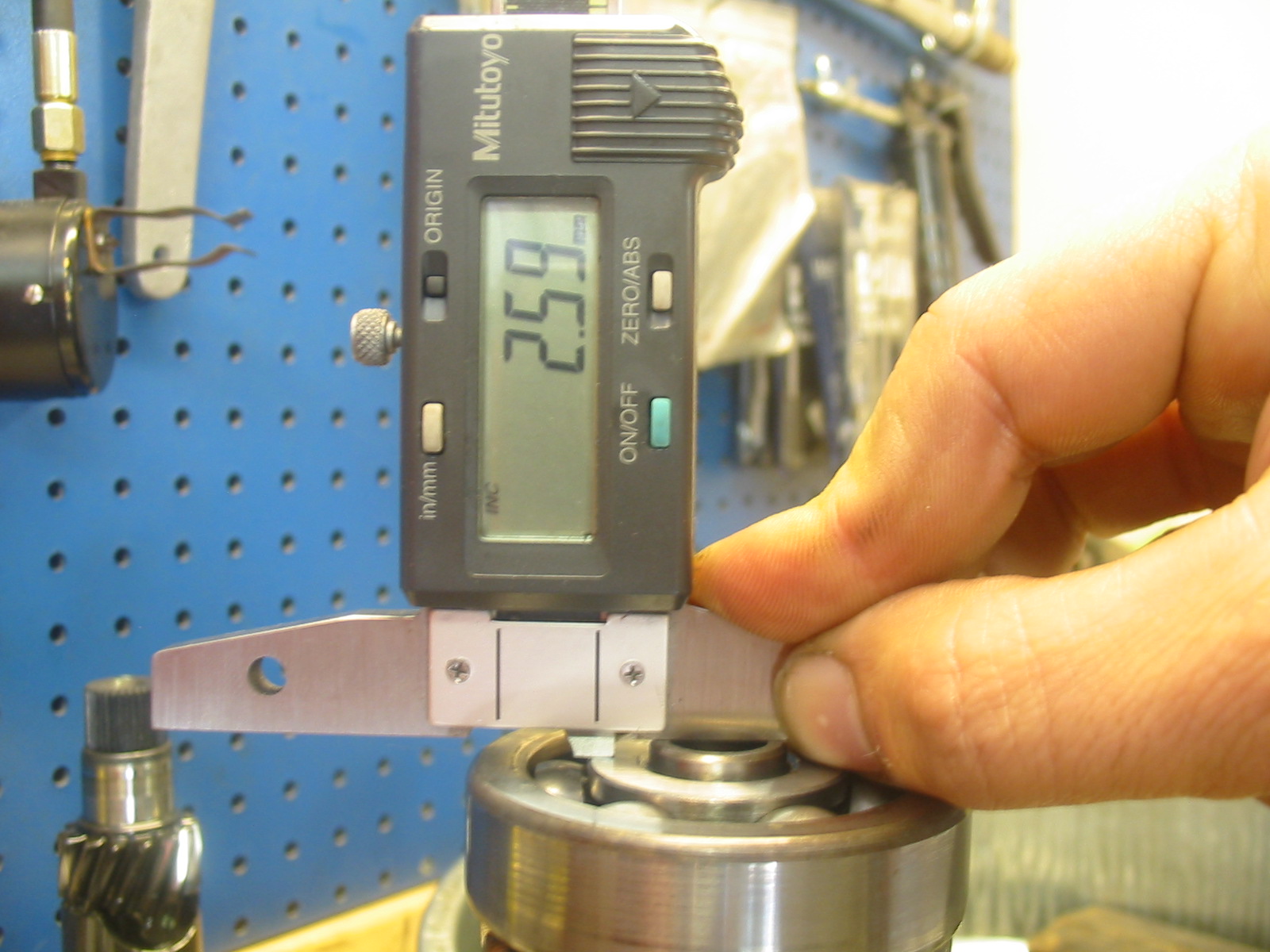
The 5th gear wheel rides on the second section and sits against the end of the flutes (with a washer in between). You can see wear rings on both shafts from the gear, which cocks sideways a bit under load. When there is enough wear, the shaft gets replaced or repaired.

The front bearing takes the brunt of this load because of the helical gear. Inspecting the bearing, you can easily see a heavy wear groove in the front side of the outer race, but I don't think my camera can capture it. The rear bearing (which was also running with axial load, but not as badly) shows some wear but not nearly as much.
Often, this isn't noticed until things start to break apart. Aside from the fact that he'd toasted his crankshaft, this guy was sort of lucky that his bike was here, and this was found before it got too bad.
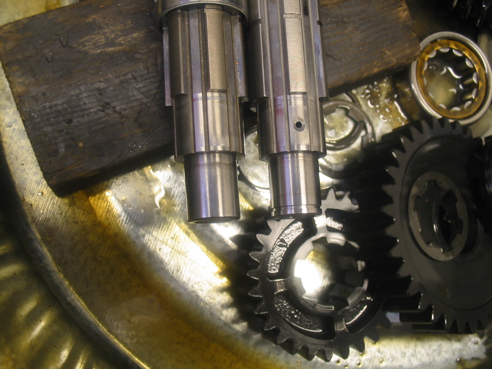
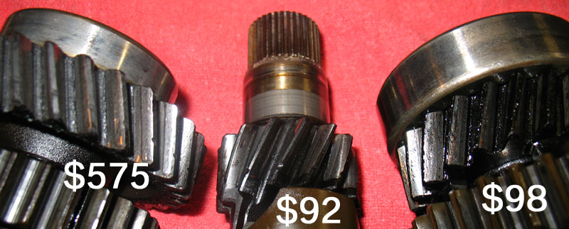
Here's one example of what happens when it does get bad. In this case the 'circlip bearing' (right) developed excessive clearance, allowing it to move away from the intermediate shaft (left). The teeth were therefore not fully engaging, leading to accelerated tooth wear. You can see the ridges in each tooth on the intermediate shaft gear. The input shaft gear (center) wore due to their contact with the worn teeth on the intermediate. The intermediate shaft is only available from BMW as a complete unit, hence the high cost, although they can be repaired if a replacement gear is available.

The damage shown to the left is what happens when the inner bearing race disappears and the end of the shaft acts as the race. This is, umm, non-repairable.

